How to Test a Stator on ATV: 4 Tests to Diagnose It
Sep 15 2026
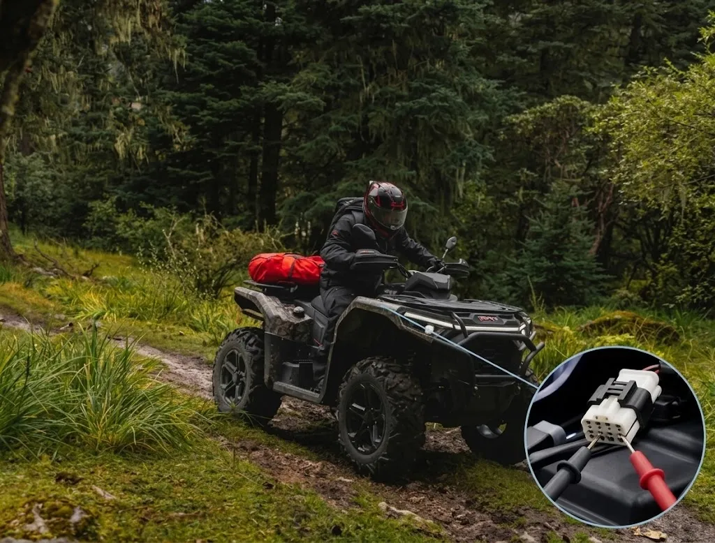
If you want to know how to test a stator on ATV, the core idea is simple. Use a multimeter for a static resistance check and a running AC voltage check. The stator sits at the center of the ATV charging system. Engine rotation drives the rotor. The rotor spins past the stator. AC voltage shows up. Downstream circuits rectify and regulate that AC, then send it to the electrical system and battery.
A battery that keeps going flat, or an ATV that develops starting problems, can point to the stator. It can also point somewhere else. The battery, regulator/rectifier, wiring, and other electrical parts can produce the same symptoms. So before unplugging the stator connector, check the basic external electrical parts. The charging circuit works as a chain. One bad connection, or one faulty related part, can mimic a bad stator.
What to Check Before Testing the ATV Stator
Battery: Before you test the stator, make sure the ATV battery is charged and can hold that charge. A weak battery makes charging system diagnosis harder. An old battery can show low battery symptoms. So can one that will not hold voltage. The charging system may be working fine.
Battery Terminals and Wiring: Before component-level tests, check the battery terminals, wiring, and stator connector. Loose parts, corrosion, damaged insulation, any visible issue, all of it counts. Check for oxidized terminals. Check for loose terminals. Look for broken wire insulation. Doing this first can save you from tearing things apart for no reason.
Regulator/Rectifier: The stator is only one part of the charging system. The regulator/rectifier also helps keep electrical supply steady to the battery. When that regulator/rectifier fails, the battery may not receive the correct charging voltage.
How to Test a Stator on ATV With a Multimeter
A digital multimeter is the most common tool for stator testing. The key to how to test a stator on ATV is to separate static tests with the engine off from dynamic tests with the engine running. That matters for accurate readings, and it matters for safety.
Before You Start: Static vs. Dynamic Tests
Static Tests --- Engine OFF: Resistance and ground tests should be performed with the ignition off and the stator connector disconnected as required by the service procedure. With no power and the stator unplugged, outside voltage will not mess up the reading, and you are less likely to damage the multimeter.
Dynamic Test --- Engine RUNNING: AC voltage testing requires the engine to run, so keep hands, test leads, clothing, and other loose objects away from hot or moving components. This test involves spinning parts and hot areas, so pay attention.
Tools You Need
A digital multimeter is a must. Auto-ranging helps. You also need the official service manual for your model, plus common tools to reach the stator connector.
Safety Note
Never measure resistance (Ohms) on a live circuit. Turn the ignition completely OFF. Disconnect the stator connector before resistance or ground tests. Measuring resistance on a powered circuit can damage your meter.
1. Check Stator Resistance
Engine off. Disconnect the stator connector. Set the multimeter to resistance (Ohms). Then use model-specific service info to identify the correct terminals. Measure resistance between the required terminals. A resistance test shows how well the stator windings conduct inside.
On a single-phase stator, you usually measure between its two output terminals. For a three-phase stator, measure each pair, A-B, B-C, and A-C, then compare readings for consistency. Those three readings should usually stay reasonably consistent. If one reading is far off from the others, that phase winding may have a problem, but confirm with the model service manual.
Compare the readings with the manufacturer's specified resistance range. Do not apply one universal value. Specs vary by model, so always use the correct service manual for your machine.
2. Check for a Short to Ground
Check each stator terminal against ground according to the manufacturer's test procedure. Where an open circuit is specified, there should be no unwanted continuity between the stator winding and ground. A ground test checks for unexpected continuity between the stator winding and frame ground.
Touch the multimeter probes to a stator terminal and a good metal ground. If you see continuity or a resistance reading that does not match the service manual, there may be a short to ground or an insulation fault. Confirm the stator and related wiring further.
3. Measure AC Voltage Output
Switch the multimeter to AC voltage and start the ATV. Measure the required stator terminal pairs at the RPM and test conditions specified by the manufacturer, then compare the readings with the applicable specification. This dynamic test measures the AC voltage the stator makes while running.
For a three-phase system, measure A-B, B-C, and A-C. Check that the readings stay reasonably consistent. Follow the service manual for RPM and test conditions. Normally, output changes with RPM, and the three phases should stay reasonably consistent.
4. Compare the Readings Across the Tests
Putting several test results side by side gives you a fuller picture of the stator's physical condition:
Test Type | Normal Indication | Possible Problem |
Resistance Test | Within manufacturer specification | Winding fault |
Ground Test | No unwanted continuity | Short to ground |
AC Output Test | Within specification and reasonably consistent | Possible stator, rotor, wiring, or connection issue |
One abnormal reading does not automatically mean the stator needs replacement. Confirm the result against the model-specific spec. Think about the rest of the charging system before replacing a component.
Before swapping parts, rule out rusted connectors or loose terminals. Those can look like a stator problem.
How to Tell If the Stator Is the Problem
If the readings are within specification, the stator may be working normally. Resistance, ground, and AC output all fall inside the applicable specs. That does not clear the whole charging system. The ATV can still have a charging problem. Keep checking the battery, regulator/rectifier, wiring, and connections. Under the current test conditions, the stator looks fine. If the ATV still will not charge, move on to the regulator/rectifier, battery, harness, and connections.
If the resistance or ground test fails, a reading outside spec can point to a winding or insulation problem. Confirm it with the ATV's specific service procedure. A clearly bad static resistance reading can suggest a stator winding or insulation fault. So can unwanted ground continuity. Other test results should confirm it.
If the AC output is abnormal, output below specification or significantly uneven between phases can mean the stator is contributing to the charging problem. If the readings remain unclear, a broader diagnostic process may be necessary. Normal static resistance with abnormal dynamic AC voltage means static tests alone may not find the issue. Rotor condition, stator windings, wiring connections, and further tests in the service manual all need a look.
Conclusion
These basic checks help ATV owners understand whether a charging problem may involve the stator or another part of the electrical system. They also help when maintaining or diagnosing current SWM ATV models.
Check the battery, connections, and charging system in the right order. Then use resistance, ground, and AC output tests to judge whether the stator may be the source. If tests do not clearly locate the problem, follow the model-specific service manual and professional diagnostic results.
-
Sep 20 2026
learn more
 How to Read ATV Tire Size: 27×9-14 Explained
How to Read ATV Tire Size: 27×9-14 Explained
How to Read ATV Tire Size: 27×9-14 Explained
-
Sep 17 2026
learn more
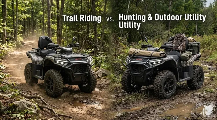 ATV Trail Riding vs Hunting: How to Choose the Right ATV
ATV Trail Riding vs Hunting: How to Choose the Right ATV
ATV Trail Riding vs Hunting: How to Choose the Right ATV
-
Sep 16 2026
learn more
 What Size UTV Do I Need? 5 Steps to Choose the Right One for You
What Size UTV Do I Need? 5 Steps to Choose the Right One for You
What Size UTV Do I Need? 5 Steps to Choose the Right One for You
-
Sep 15 2026
learn more
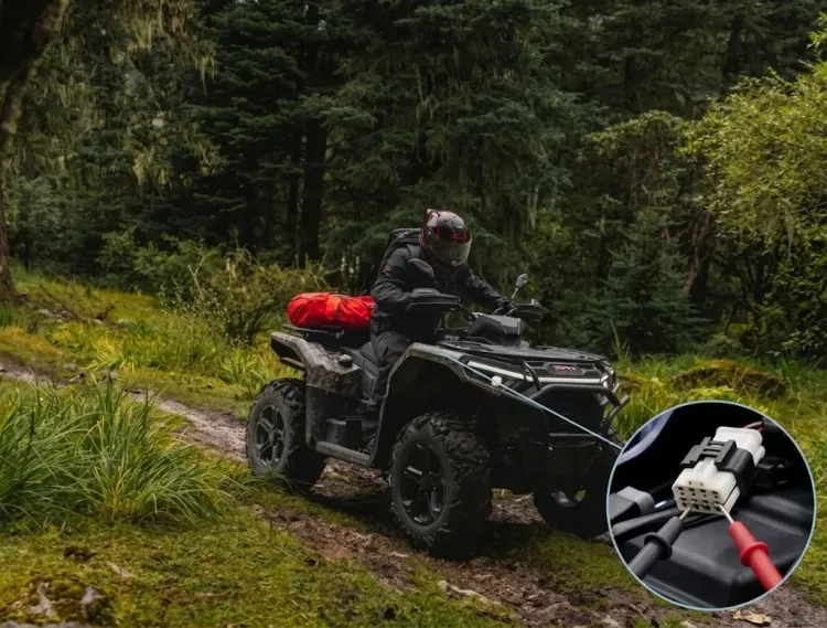 How to Test a Stator on ATV: 4 Tests to Diagnose It
How to Test a Stator on ATV: 4 Tests to Diagnose It
How to Test a Stator on ATV: 4 Tests to Diagnose It